AmpereSoft ProPlan
The user-friendly, practically oriented CAE system for electrical documentation.
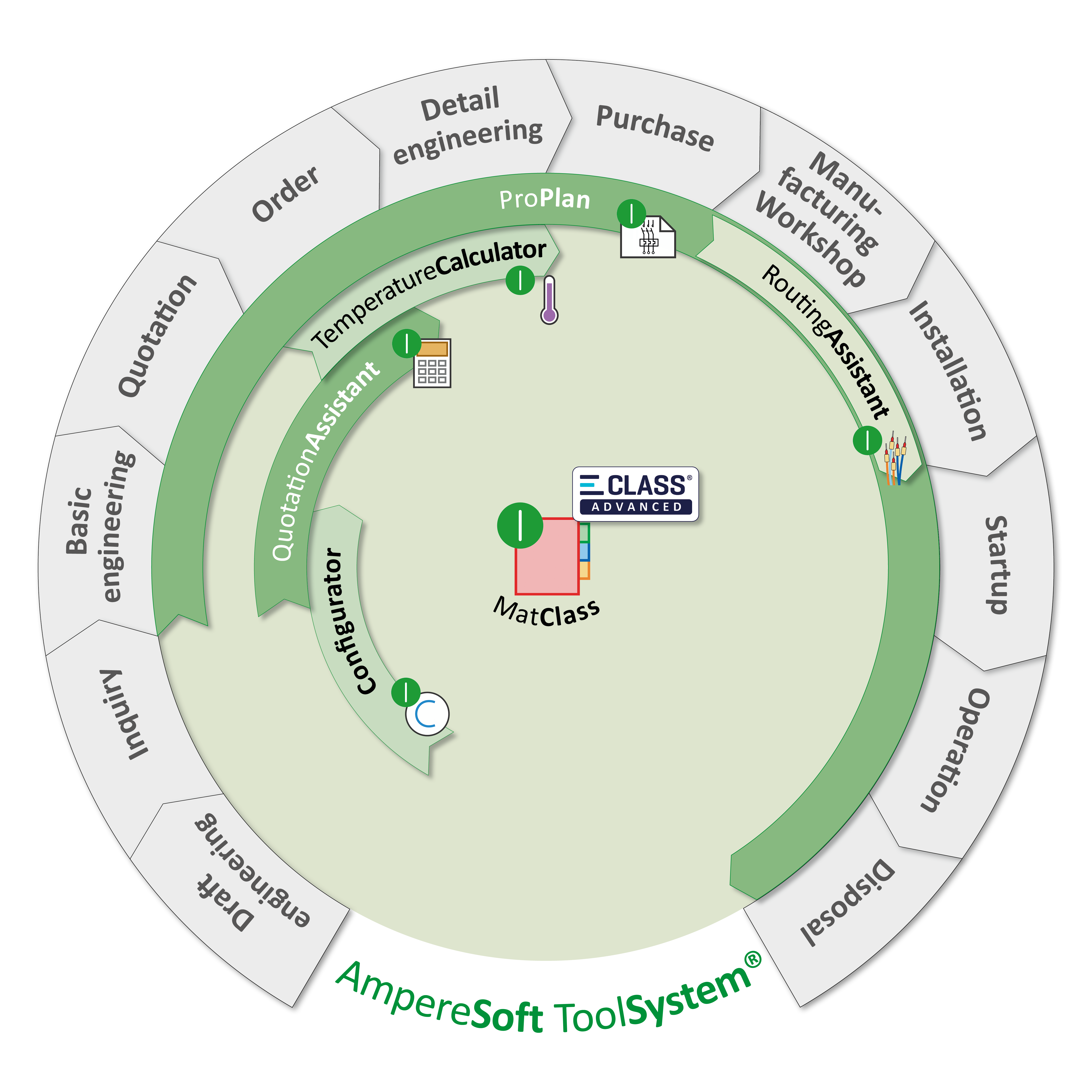
Integrated into the AmpereSoft ToolSystem

The user-friendly, practically oriented CAE system for electrical documentation.
Integrated into the AmpereSoft ToolSystem
|
|
|
|
|---|---|---|
|
Genuine online functions |
No post processing |
✔ Up-to-date display at any time |
|
Genuine object utilization |
Cohesive display in all plan types, e.g. breakdown of circuit diagram, single pole display, fluid and R&ID overviews |
✔ Modification at one point causes the modification in all displays |
|
Drag and drop functions |
Insert pictures, material and many other elements by drag and drop |
✔ Very easy and straightforward handling |
|
Material structure oriented operation |
Devices and material combinations can be taken directly from the database and used in the plans. |
✔ All parts with properties are immediately available in the parts list. |
|
Project management |
The project structuring to DIN EN 81346-1 in any number of levels and function |
✔ Seamless structuring possible with all projects sizes |
|
Material exchange |
Individual subareas or over the entire project |
✔ Optimum flexibility with types or change of manufacturer during project engineering |
|
Project Explorer |
Multiple processing of all objects with the Project Explorer; creating, copying, placing, locating etc. |
✔ Convenient processing of large projects, simple overview and processing |
|
Graphic symbols to EN/DIN, IEC |
Extensive symbol libraries |
✔ Time saving |
|
Alternative symbol management |
Assignment of several symbols to a single equipment item |
✔ Saving of different symbols for different applications can be assigned |
|
Assembly plan |
Easily created through Wizard functions, online relationship to all plan types and lists, 3D view, true to scale |
✔ Bidirectional identification to circuit diagram, time saving |
|
Single line diagram |
Direct relationship to multipole circuit diagram, assembly plans and lists |
✔ Automatic update in the event of changes |
|
P&ID diagrams |
Circuit symbols with logical links for P&ID diagrams |
✔ Creation of all documents in a single project; logically interlinked |
|
Fluid diagrams |
Circuit symbols with logical links for circuit diagrams for hydraulics and pneumatics |
✔ Creation of all documents in a single project; logically interlinked |
|
XML-based form creation |
Lists for terminals, cables, wires, totals, individual items, PLCs etc. and overviews in modern XML format |
✔ Fast evaluation at the click of a mouse; individual adaption of forms; always up-to-date |
|
Potentials management |
Cross-system, linked or star |
✔ Clearer overview, wiring support |
|
Modules |
Simple creation of wired switchgear and controlgear assemblies and standard circuits |
✔ Fast compilation of documentation |
|
Efficient copy functions |
The versatile copy options enable selected elements or sections to be copied logically. |
✔ Reach your goal faster with modular copying |
|
User-defined foreign language database |
All texts can be displayed in any language with the click of a mouse (Unicode capable), maintenance of standard texts. |
✔ Worldwide use possible, text maintenance, reading in or out of texts, e.g. a translation service provider |
|
Creation of dimension diagrams |
Automatic creation of device dimension diagrams based on the dimension entries in the database, 3D functionality |
✔ Time saving |
|
Assignable terminal connections |
Can be assigned and placed remotely. |
✔ Greater clarity during engineering |
|
Graphic interfaces |
DXF, DWG, VNS, PDF, BMP, JPG, TIF |
✔ Seamless connection with other graphic programs |
|
Reading in and output of DXF, DWG files |
Reading in and output of extensive DXF drawings (e.g. ground plans) and complete circuit diagrams |
✔ Plans can be included in the ground plan; possibility of reading in from other circuit diagrams |
|
Open XML interfaces |
Scripting function and link to AutomationML |
✔ Transparency; user-defined scripts can also be integrated |
|
Interfaces to drilling machines and robots |
Graphic features can be read in directly by the drilling machines of Kiesling and Steinhauer; automatic assembly of mounting plates |
✔ Seamless workflow, production process optimization |
|
Wiring output |
Cable assembly via the CadCabel interface and wiring machines |
✔ Makes work easier, production process optimization |
|
Marking / label printout |
Data transfer to device/terminal l abeling software of various manufacturers |
✔ Benefit during manufacturing |
|
Management of PLC texts |
Of all manufacturers through direct importing and exporting of the assignment lists |
✔ Makes work easier by preventing duplicate entries |
|
Writing material database |
Continually updated manufacturer databases and neutral material data |
✔ List output with actual products and data |
Other functions: QR code, AutoRouting, temperature calculation, calculation, as well as search and management options
Noticeably shorten your engineering process with automated function sequences. The key: standardized material data that was classified, for example, with ECLASS ADVANCED. This enables users of the ProPlan CAE solution to generate symbols quickly and simply. A number of symbol trays are also provided.
ProPlan's auto-routing function offers you the latest generation of engineering. Using x, y and z coordinates as a basis, the 3D auto-routing function enables wiring to be routed automatically, taking cabinet doors and other depth dimensions into account. The optimization of your wiring lengths also takes into account whether cable ducts are to be used or not.
Users benefi t from the simple and dynamic generation of documents such as parts lists, PLC lists, cross-reference lists, EQID labels, terminal plans, as well as cable and wiring plans.


ProPlan features its own multi-lingual database. This makes it possible to activate and deactivate translation functions selectively. These can cover all languages, even those with Cyrillic letters. The database can output files and, after processing by a translation service provider for example, read them back in.
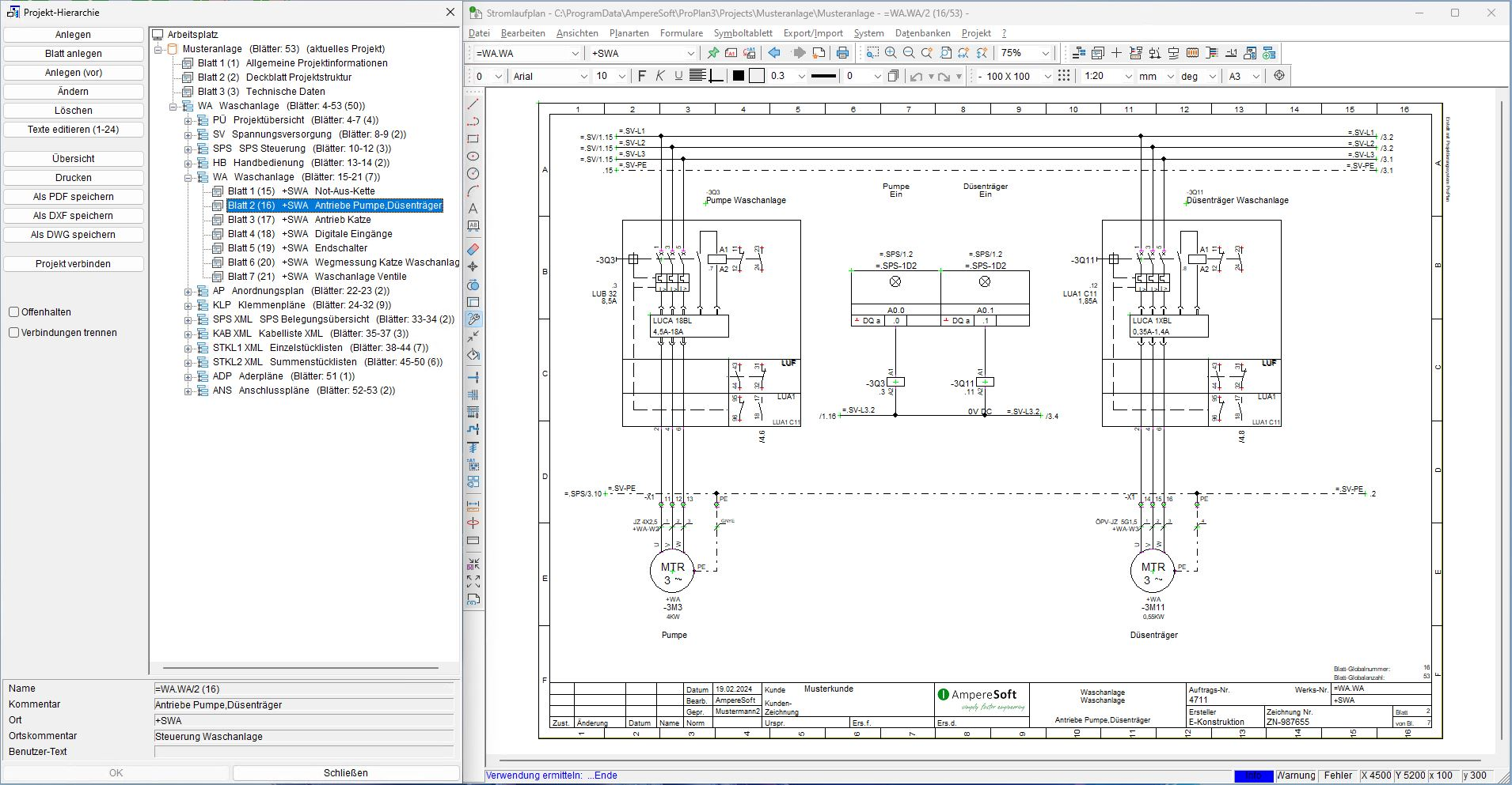
The project management function makes it possible to structure the projects at any level and enables them to function in accordance with DIN EN 81346-1. This complete overview of the project hierarchy in a tree structure with a direct link to the relevant plan types speeds up the planning process. Plan your documentation for power station construction and off shore plants without any problems in accordance with RDS-PP.
The so-called ProjectExplorer represents the core of ProPlan. You use this to manage all your materials and all other information that you require for the engineering. Comprehensive mass maintenance and copy options support you in the rapid engineering of your plant. For example, you can create several hundred meters of cable, switches, contactors etc. and can start engineering immediately. If the EQID or cable numbers have already been provided by the customer, you can read in these EQIDs via one of the many interfaces available.
We have been a driving force in the area of open and standardized interfaces and off er you a range of possibilities in the field of electrical engineering using our own scripting. Whether it's DXF, DWG, PDF, BMP, JPG, TIF, EXCEL, BMEcat on the one hand or the connection of other systems via XML / Automation-ML on the other: Nothing now stands in the way of you connecting to automation portals or ERP solutions such as SAP, ProAlpha or other software systems. A lot can be carried out by drag and drop.
All material data also provides the basis for the feature enhancements TemperatureCalculator, QuotationAssistant and various product configurators belonging to the ToolSystem. Preconfigured interfaces enable you to also exchange the data here trouble-free. You can thus automatically carry out the legally required temperature calculation of your switchgear assembly up to 1,600A, complete the individual verification at the same time and also determine the price of your engineering. In addition to the already mentioned interfaces, QuotationAssistant also offers the possibility to read in the data in a GAEB format and also output it. The creation of public tenders thus becomes child's play.

Ever wanted to assemble wires but your CAE system doesn't provide a suitable routing system for calculating wire lengths and a transfer format for the assembly machine?
The parts and wiring list from your CAE system are read into Ampere Soft RoutingAssistant via a confi gurable import interface.
With the ECLASS ADVANCED data of the used equipment, you generate the symbols in a twinkling of the eye and easily create the fill assembly plan.
You can carry out the routing at the click of a button, optimize the wire routing and add any missing connections (even without a circuit diagram! ). You can naturally add, edit and also automatically calculate the wire properties (wire color, wire cross section etc.) before routing, based on the data of the circuit diagram, the technical features of the components used and a configurable set of rules.
AmpereSoft RoutingAssistant is available as an add-on for your existing AmpereSoft ProPlan license or as a "stand-alone solution" alongside your existing CAE system.
The cross-project search and maintenance tool for working with AmpereSoft ProPlan.
- Find the required AmpereSoft ProPlan project in your directory structures (local / network) quickly and easily by using project attributes (fixed texts), key texts, plan texts, symbol names and material attributes.
- Maintain attributes, or symbols and material for all projects or specific ones.
- Use the effective mass management tool for importing both materials and symbols, as well as for archiving, compressing and outputing the selected ProPlan projects.
- Use the simple drag and drop functionality to open a ProPlan project or create a new one. If required, simply use an existing project as a sample for the new project.

ProPlan is the pre-tested tool for professional datail engineering. The integration into the ToolSystem allows the smooth transfer of the projects from the configuration and costing as well as the use of the project data for automated production. These include e.g. the autorouting for the cable assembly and the data transfer to drilling machines.